6.11在Deferred Shading引擎中添加阴影能力
问题
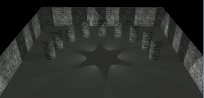
虽然你已经掌握了基本的计算机实时光照,但你应该注意到光源还没有投射出阴影。这是因为pixel shader是基于光线与法线的夹角计算光照的。直到现在,pixel shader还没有考虑到光线与像素间的物体。
阴影映射(shadow mapping)技术在我的网站(http://www. riemers. net)的第三个系列中加以介绍,这个技术可以对一个光源生成正确的阴影,但是你想用deferred渲染的方法实现。
解决方案
在场景中添加阴影的一个极好的方法是阴影映射技术,我已经在我的网站上详细介绍了 (http://www.riemers.net)。
简而言之,阴影映射技术将每个像素与光源之间的真实距离与从光源看起来的距离做比较。如果真实距离大于从光源看来的距离,那么必定有个对象处于相机与像素之间,因此这个像素不被照亮。
要允许这种比较,场景首先应该绘制成从光源看起来的情况,这样像素到光源的距离可以被存储在一张纹理中。
如果你想实现deferred版本的阴影映射技术,必须首先为每个光源生成一张深度贴图。完成这张贴图后,阴影映射的比较就可以施加在deferrded渲染的第二步中。
工作原理
本教程完全建立在前一个教程的基础上。前一个教程的第一步保持不变,因为你仍需要屏幕上所有像素的颜色,法线和深度值。
生成阴影贴图
XNA代码
在第二步中获取一个光源的光照值之前,你需要为这个光源生成阴影贴图。这个阴影贴图包含场景和光源间的距离。你还需要添加一个渲染目标和两个变量:一个存储距离,一个黑色图像用来重置另一个:
RenderTarget2D shadowTarget; Texture2D shadowMap; Texture2D blackImage;
在LoadContent方法中初始化渲染目标和黑色图像:
shadowTarget = new RenderTarget2D(device, width, height, 1, SurfaceFormat.Single);
blackImage = new Texture2D(device, width, height, 1, TextureUsage.None, SurfaceFormat.Color);
然后找到GenerateShadingMap方法。这个方法使用alpha混合将所有光源的光照值混合在一起添加到一张纹理中。这一步不需要,因为你需要在两个混合操作之间生成一张新的阴影贴图,这会导致阴影贴图混合到shading贴图中。
不用alpha混合,添加完每个光源的光照值后你将保存shading贴图。但首先要使用黑色图像删除shading贴图:
private Texture2D GenerateShadingMap()
{
    shadingMap = blackImage;
    for (int i = 0; i < NumberOfLights; i++)
    {
        RenderShadowMap(spotLights[i]);
        AddLight(spotLights[i]);
    }
    return shadingTarget.GetTexture();
}
对每个光源首先调用RenderShadowMap方法,这个方法会在shadowMap变量中存储光源的阴影贴图。基于这张阴影贴图,光源会将它的光照值添加到shading贴图中。
阴影贴图需要包含从光源看来的距离值。所以,每个光源需要定义View和Projection矩阵,这需要扩展SpotLight结构:
public struct SpotLight
{
    public Vector3 Position;
    public float Strength;
    public Vector3 Direction;
    public float ConeAngle;
    public float ConeDecay;
    public Matrix ViewMatrix;
    public Matrix ProjectionMatrix;
}
对一个聚光灯来说,定义这两个矩阵非常容易:
spotLights[i].ViewMatrix = Matrix.CreateLookAt(lightPosition, lightPosition + lightDirection,lightUp);
float viewAngle = (float)Math.Acos(spotLights[i].ConeAngle);
spotLights[i].ProjectionMatrix = Matrix.CreatePerspectiveFieldOfView(coneAngle * 2.0f, 1.0f, 0.5f, 1000.0f);
viewAngle基于聚光灯的光锥。通过这种方式,渲染目标的区域可以得到最优化的使用。
RenderShadowMap方法将这些矩阵传递到ShadowMap effect(下面就会定义)中。之后,场景从相机看来的方式被绘制,距离保存到shadowMap纹理中。
private void RenderShadowMap(SpotLight spotLight)
{
    device.SetRenderTarget(0, shadowTarget);
    effectShadowMap.CurrentTechnique= effectShadowMap.Techniques["ShadowMap"];
    ffectShadowMap.Parameters["xView"].SetValue(spotLight.ViewMatrix);
    effectShadowMap.Parameters["xProjection"].SetValue(spotLight.ProjectionMatrix);
    RenderScene(effectShadowMap); device.SetRenderTarget(0, null);
    shadowMap = shadowTarget.GetTexture();
}
HLSL代码
HLSL代码很简单。因为3D场景需要变换为2D屏幕坐标,effect需要World,View和 Projection矩阵。 要匹配RenderScene方法还需要设置一个纹理,所以effect也包含xTexture变量,虽然这里没有用到这个变量
float4x4 xWorld;
float4x4 xView;
float4x4 xProjection;
Texture xTexture;

struct VertexToPixel
{
    float4 Position : POSITION;
    float4 ScreenPos : TEXCOORD1;
};

struct PixelToFrame
{
    float4 Color : COLOR0;
}
vertex shader需要计算2D屏幕坐标。这个屏幕坐标还包含深度值让pixel shader输出。因为POSITION语义无法在pixel shader中访问,你要将它复制到ScreenPos变量中。
vertex shader非常简单,因为它做的就是将3D位置转换为2D屏幕位置:
VertexToPixel MyVertexShader(float4 inPos: POSITION0, float3 inNormal: NORMAL0)
{
    VertexToPixel Output = (VertexToPixel)0;
    float4x4 preViewProjection = mul(xView, xProjection);
    float4x4 preWorldViewProjection = mul(xWorld, preViewProjection);
    Output.Position = mul(inPos, preWorldViewProjection);
    Output.ScreenPos = Output.Position;

    return Output;
}
pixel shader接受屏幕坐标。因为这是一个齐次(homogeneous)向量,所以在使用前要将前三个分量除以第四个分量。pixel shader生成深度值输出。
PixelToFrame MyPixelShader(VertexToPixel PSIn) : COLOR0
{
    PixelToFrame Output = (PixelToFrame)0;
    Output.Color.r = PSIn.ScreenPos.z/PSIn.ScreenPos.w;

    return Output;
}
下面是technique定义:
technique ShadowMap
{
    pass Pass0
    {
        VertexShader = compile vs_2_0 MyVertexShader();
        PixelShader = compile ps_2_0 MyPixelShader();
    }
}
根据光照计算添加阴影映射
XNA代码
绘制了阴影贴图后,调用AddLight方法。这个方法首先开启shadingTarget和DeferredSpotLight technique。这个方法和technique主要部分与前一个教程相同,除了一些小变化。在每个光源的最后,shadingTarget的当前内容被保存到shadingMap纹理中。通过xPreviousShadingMapContents变量将这个内容传递到下一个光源中,你还要传递阴影贴图。
private void AddLight(SpotLight spotLight)
{
    device.SetRenderTarget(0, shadingTarget);
    effect2Lights.CurrentTechnique = effect2Lights.Techniques["DeferredSpotLight"];
    effect2Lights.Parameters["xPreviousShadingContents"].SetValue(shadingMap);
    effect2Lights.Parameters["xNormalMap"].SetValue(normalMap);
    effect2Lights.Parameters["xDepthMap"].SetValue(depthMap);
    effect2Lights.Parameters["xShadowMap"].SetValue(shadowMap);
    effect2Lights.Parameters["xLightPosition"].SetValue(spotLight.Position);
    effect2Lights.Parameters["xLightStrength"].SetValue(spotLight.Strength);
    effect2Lights.Parameters["xConeDirection"].SetValue(spotLight.Direction);
    effect2Lights.Parameters["xConeAngle"].SetValue(spotLight.ConeAngle);
    effect2Lights.Parameters["xConeDecay"].SetValue(spotLight.ConeDecay);

    Matrix viewProjInv = Matrix.Invert(fpsCam.ViewMatrix * fpsCam.ProjectionMatrix);
    effect2Lights.Parameters["xViewProjectionInv"].SetValue(viewProjInv);
    effect2Lights.Parameters["xLightViewProjection"].SetValue(spotLight.ViewMatrix * spotLight.ProjectionMatrix);

    effect2Lights.Begin();
    foreach (EffectPass pass in effect2Lights.CurrentTechnique.Passes)
    {
        pass.Begin();
        device.VertexDeclaration = fsVertexDeclaration;
        device.DrawUserPrimitives<VertexPositionTexture>(PrimitiveType.TriangleStrip, fsVertices, 0, 2);
        pass.End();
    }
    effect2Lights.End();
    device.SetRenderTarget(0, null);
    shadingMap = shadingTarget.GetTexture();
}
HLSL代码确保effect可以接受新的纹理:
Texture xShadowMap;
sampler ShadowMapSampler = sampler_state
{
    texture = <xShadowMap>;
    magfilter = LINEAR;
    minfilter = LINEAR;
    mipfilter=LINEAR;
    AddressU = mirror;
    AddressV = mirror;
};

Texture xPreviousShadingContents;
sampler PreviousSampler = sampler_state
{
    texture = <xPreviousShadingContents>;
    magfilter = LINEAR;
    minfilter = LINEAR;
    mipfilter=LINEAR;
    AddressU = mirror;
    AddressV = mirror;
};
唯一的变化在pixel shader中。你想获取点和光源之间的真实距离和存储在阴影贴图中的距离。如果存储在阴影贴图中的距离小于真实距离,说明有一个物体处于光源和像素之间,这个像素不会被当前光源照到。要找到真实距离,需要通过光照的ViewProjection矩阵转换3D位置。在除以它的齐次分量(译者注:即w分量,第四个分量)后,这个距离的Z分量就可以容易地使用了。
//find screen position as seen by the light
float4 lightScreenPos = mul(worldPos, xLightViewProjection);
lightScreenPos /= lightScreenPos.w;
然后,你想获取存储在阴影贴图中的距离。首先需要知道到哪采样阴影贴图,将lightScreenPos的分量从[–1,1]的屏幕位置区间映射到[0,1]纹理坐标区间,这和前一个教程一样:
//find sample position in shadow map
float2 lightSamplePos;
lightSamplePos.x = lightScreenPos.x/2.0f+0.5f;
lightSamplePos.y = (-lightScreenPos.y/2.0f+0.5f);
现在可以采样存储在阴影贴图中的深度值了。检查这个距离是否小于真实距离,表示像素是否被当前光源照亮:
//determine shadowing criteria
float realDistanceToLight = lightScreenPos.z;
float distanceStoredInDepthMap = tex2D(ShadowMapSampler, lightSamplePos);
bool shadowCondition = distanceStoredInDepthMap <= realDistanceToLight - 1.0f/100.0f;
最后,基于shadowCondition和coneCondition判断像素是否被照亮。这个shading值被添加到shadingMap中的原有值上,这是在pixel shader中的最后一行代码中执行的。
下面是完整的pixel shader代码:
PixelToFrame MyPixelShader(VertexToPixel PSIn) : COLOR0
{
    PixelToFrame Output = (PixelToFrame)0;

    //sample normal from normal map
    float3 normal = tex2D(NormalMapSampler, PSIn.TexCoord).rgb;
    normal = normal*2.0f-1.0f;
    normal = normalize(normal);

    //sample depth from depth map
    float depth = tex2D(DepthMapSampler, PSIn.TexCoord).r;

    //create screen position
    float4 screenPos;
    screenPos.x = PSIn.TexCoord.x*2.0f-1.0f;
    screenPos.y = -(PSIn.TexCoord.y*2.0f-1.0f);
    screenPos.z = depth;
    screenPos.w = 1.0f;

    //transform to 3D position
    float4 worldPos = mul(screenPos, xViewProjectionInv);
    worldPos /= worldPos.w;

    //find screen position as seen by the light
    float4 lightScreenPos = mul(worldPos, xLightViewProjection);
    lightScreenPos /= lightScreenPos.w;

    //find sample position in shadow map
    float2 lightSamplePos;
    lightSamplePos.x = lightScreenPos.x/2.0f+0.5f;
    lightSamplePos.y = (-lightScreenPos.y/2.0f+0.5f);

    //determine shadowing criteria
    float realDistanceToLight = lightScreenPos.z;
    float distanceStoredInDepthMap = tex2D(ShadowMapSampler, lightSamplePos);
    bool shadowCondition = distanceStoredInDepthMap <= realDistanceToLight - 1.0f/100.0f;

    //determine cone criteria
    float3 lightDirection = normalize(worldPos - xLightPosition);
    float coneDot = dot(lightDirection, normalize(xConeDirection));
    bool coneCondition = coneDot >= xConeAngle;

    //calculate shading
    float shading = 0;
    if (coneCondition && !shadowCondition)
    {
        float coneAttenuation = pow(coneDot, xConeDecay);
        shading = dot(normal, -lightDirection);
        shading *= xLightStrength;
        shading *= coneAttenuation;
    }

    float4 previous = tex2D(PreviousSampler, PSIn.TexCoord);
    Output.Color = previous + shading;

    return Output;
}
代码
这个教程使用与教程6-10相同的代码,但GenerateShadingMap,RenderShadowMap和 AddLight方法有所变化,而这几个方法前面已经写过了。
发布时间:2009/9/30 10:48:20 阅读次数:7384