5.12 创建自己的顶点格式
问题
顶点用来存储从XNA项目发送到显卡的数据。一个顶点格式包含存储在顶点中的数据的描述。XNA框架自带有默认的顶点格式,从简单的VertexPositionColor到 VertexPostionNormalTexture格式。
但是,如果你需要顶点带有额外的数据,例如切线或时间数据,就需要定义自己的顶点格式。如果要在顶点shader中使用这个数据,这一步是必须的。所以,只有编写自定义的顶点和像素shader时,你才需要定义一个自定义顶点格式。
解决方案
顶点格式定义了在顶点中存储何种类型的数据,何种数据可以被vertex shader访问。例如,当使用VertexPositionColor格式的顶点时,VertexPositionColor结构告知显卡顶点将包含位置和颜色数据,以及在数据流中的何处可以找到这些数据。
顶点格式是XNA代码和vertex shader之间的链接。首先,顶点格式表示数据在数据流中如何定位,如图5-24上面的灰色曲线所示,表明位置和颜色数据位于数据流的何处。
只要显卡需要从顶点中绘制三角形,它就需要将数据流还原为顶点。
然后,显卡需要将每个顶点分离成位置和颜色数据。所以顶点格式还告知显卡在哪切割数据流,如图5-24下面的灰色曲线所示。
最后,对每个重建的顶点,使用位置和颜色数据调用vertex shader。
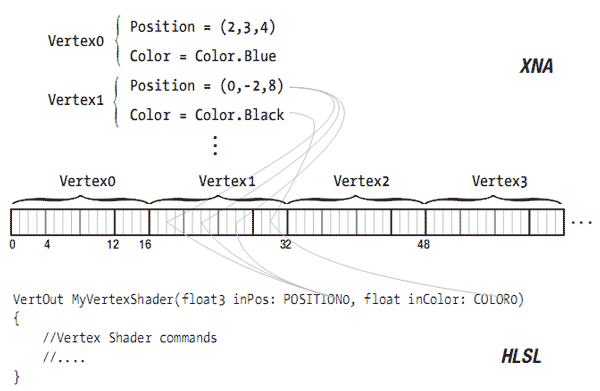
图5-24 顶点格式表示在数据流中可以找到哪些数据。
工作原理
本教程中,你将创建自己的VertexPositionColor结构学习基础知识。在第二部分,你会将这个结构扩展为一个新的,自定义的顶点格式。
重新创建VertexPositionColor结构
这部分你将创建一个MyVertexPositionColor结构(和VertexPositionColor结构相同)学习基础知识。 VertexPositionColor结构能够储存所有必要的信息。它由三部分组成:
- 每个顶点自身的数据,为一个Vector3存储位置和一个Color
- 一个顶点的大小,这样显卡可以将数据流切割成单独的顶点
- VertexElements,它可以告知显卡每个顶点包含何种数据,显卡应该如何切割顶点以获得对应的数据。
第1步
首先添加这个结构:
public struct MyVertexPositionColor
{
    public Vector3 Position;
    public Color Color;
    public MyVertexPositionColor(Vector3 position, Color color)
    {
        Position = position;
        Color = color;
    }
}
这个结构可以存储一个表示位置的Vector3和颜色。这足以创建一个顶点并将他们发送到显卡。
第2步
需要知道一个顶点要占据多少字节,这样显卡才能完美地将数据流切割成独立的顶点。在结构中添加如下代码行:
public static readonly int SizeInBytes = sizeof(float) * (3 + 1);
因为这个信息对所有顶点来说都是一样的,而且只需读取它,所以可以将它设置为static readonly。
每个顶点包含一个Vector3和一个Color。Vector3由三个浮点数组成,Color为一个浮点数。所以,一个顶点占据的字节大小为(一个浮点数占据的字节大小)*(3+1)。
注意:一个浮点数为4个字节,所以你可以将这个值表示成4*(3+1) = 16。看图5-24验证一下每个顶点都包含16的字节,每个新顶点开始的字节序号都是16的倍数。这就是显卡将字节流分割成独立的顶点的方式。
通过第二步,显卡就可以知道如何将字节流切割成独立的顶点。
第3步
最后,在结构中添加以下代码:
public static readonly VertexElement[] VertexElements =
{
    new VertexElement(0, 0, VertexElementFormat.Vector3, VertexElementMethod.Default,VertexElementUsage.Position, 0),
    new VertexElement(0, sizeof(float)*3, VertexElementFormat.Color, VertexElementMethod.Default, VertexElementUsage.Color, 0),
};
上面的信息显示包含在一个顶点中的数据类型以及数据位于顶点的哪个字节中。第一个VertexElement 表示每个顶点包含位置数据,第二个表示颜色数据。让我们依次讨论每个参数。
第一个参数表示到哪个数据流获取数据。只有高级程序会使用多个顶点数据流,所以通常为0。
技巧:多个顶点流是很有用的,如果Position数据保持不变而Color数据需要频繁更新时,可以将 数据分在两个顶点流中,Position数据保持不变,你只需将Color数据从CPU传递到GPU中即可。
第二个参数表示到哪找到数据。它是顶点中的数据的字节索引。因为Position数据是第一个数据,你指定在索引0位置找到它。Color数据在Position数据之后,所以你必须知道Position数据有几个字节。Position数据占据三个浮点数,所以你指定为sizeof(float)*3 (因为一个浮点数为4个字节,也可以用12表示)。看一下图5-27:Color数据在字节12处开始。
第三个参数表示保存到数据流中的数据格式,它是数据的基类型。对Position而言是Vector3,对Color而言是Color类型。
第四个参数只用于高级和特定的硬件扩展,例如在N-Patching中,一个几何体的三角形数量会基于法线进行调整,这样会提高几何体的阴影质量。
第五个参数非常重要,它表示这个数据链接到哪个vertex shader的输入。再看一次图5-24,注意vertex shader的输入参数。这两个参数后面都跟有一个语义POSITION0和COLOR0。在本例中,你将数据的第一部分,包含Position数据,和POSITION0语义链接在一起。数据的第二部分链接到COLOR0语义。
最后一个参数让你指定每个语义的多个版本。它实际上指向POSITION0和COLOR0最后的0。对应的例子会在本教程的后半部分展示。
通过第三步,显卡知道了到哪获取顶点中的什么数据。在本例中,它会将0到11的字节 (3个浮点数)传递到vertex shader的POSITION0输入,12到15字节(1个浮点数)传递到COLOR0输入。
完整的MyVertexPositionColor结构
下面是现阶段的成果:
public struct MyVertexPositionColor
{
    public Vector3 Position;
    public Color Color;
    public MyVertexPositionColor(Vector3 position, Color color)
    {
        Position = position;
        Color = color;
    }

    public static readonly VertexElement[] VertexElements =
    {
        new VertexElement(0, 0, VertexElementFormat.Vector3, VertexElementMethod.Default, VertexElementUsage.Position, 0),
        new VertexElement(0, sizeof(float)*3, VertexElementFormat.Color, VertexElementMethod.Default, ~ VertexElementUsage.Color, 0),
    };

    public static readonly int SizeInBytes = sizeof(float) * (3 + 1);
}
MyVertexPositionColor结构的用法
有了这个结构,你就可以定义顶点并将它们转换到一个VertexBuffer流中,可见教程5-4的解释。但这次,你用的是自定义的格式:
private void InitVertices()
{
    myVertexDeclaration = new VertexDeclaration(device, MyVertexPositionColor.VertexElements);
    MyVertexPositionColor[] vertices = new MyVertexPositionColor[3];

    int i = 0;
    vertices[i++] = new MyVertexPositionColor(new Vector3(1, 1, -1), Color.Red);
    vertices[i++] = new MyVertexPositionColor(new Vector3(3, 5, -1), Color.Green);
    vertices[i++] = new MyVertexPositionColor(new Vector3(5, 1, -1), Color.Blue);
    vertBuffer = new VertexBuffer(device, MyVertexPositionColor.SizeInBytes * vertices.Length, BufferUsage.WriteOnly);
    vertBuffer.SetData<MyVertexPositionColor>(vertices, 0, vertices.Length);
}
第一行代码创建VertexDeclaration,它会被传递到显卡中。
中间部分的代码创建一个包含三个MyVertexPositionColors的数组,定义了一个三角形。在每个顶点中国存储了位置和颜色。要基于这个数组创建一个VertexBuffer,你还需指定一个顶点占据的字节数,所以传递了MyVertexPositionColor.SizeInBytes为参数。
下面的代码是从VertexBuffer绘制三角形,解释可见教程5-4:
basicEffect.Begin();
foreach (EffectPass pass in basicEffect.CurrentTechnique.Passes)
{
    pass.Begin();
    device.VertexDeclaration = myVertexDeclaration;
    device.Vertices[0].SetSource(vertBuffer, 0, MyVertexPositionColor.SizeInBytes);
    device.DrawPrimitives(PrimitiveType.TriangleList, 0, 1); pass.End();
}
basicEffect.End();
在绘制三角形前,你需要将VertexElements传递给显卡,这样显卡才知道如何正确地将字节流分割成有用的数据。
自定义顶点格式
第二个例子,你将创建一个新的顶点格式,它可以存储位置,纹理坐标和一个附加的 Vector4。这可以让你在每个顶点中存储四个额外的值,图5-25显示了字节流中的这样两个顶点。
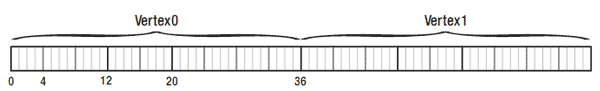
图5-25 包含两个MyCustomVertexFormats的字节流
这是一个新结构,你仍要定义三个主要部分:
public struct MyCustomVertexFormat
{
    public Vector3 Position;
    public Vector2 TexCoords;
    public Vector4 Extra;

    public MyCustomVertexFormat(Vector3 Position, Vector2 TexCoords, Vector4 Extra)
    {
        this.Position = Position;
        this.TexCoords = TexCoords;
        this.Extra = Extra;
    }

    public static readonly VertexElement[] VertexElements =
    {
        new VertexElement(0, 0, VertexElementFormat.Vector3, VertexElementMethod.Default, VertexElementUsage.Position, 0),
        new VertexElement(0, sizeof(float)*3, VertexElementFormat.Vector2, VertexElementMethod.Default, VertexElementUsage.TextureCoordinate, 0),
        new VertexElement(0, sizeof(float)*(3+2), VertexElementFormat.Vector4, VertexElementMethod.Default, VertexElementUsage.TextureCoordinate, 1),
    };

    public static readonly int SizeInBytes = sizeof(float) * (3 + 2 + 4);
}
第一部分代码允许每个顶点存储一个Position,一个Texture坐标和一个Vector4。
接下来,将它们连接到vertex shader输入。第一个Vector3链接到POSITION0 。因为这是第一个数据项目,所以可以字节0位置找到它(第二个参数)。
第二行代码表明包含纹理坐标的Vector2链接到TEXCOORD0。Position占据三个浮点数,所以纹理坐标可以在字节sizeof(float)*3 = 12处找到。
第三行将Vector4链接到另一个TEXTURE语义,因为这可以用来传递额外的数据。因为已经用过TEXTURE0,所以你将最后一个参数设为1表明将链接到TEXTURE1。
Vector4位于Position和Texture坐标数据之后,所以Vector4可以在字节sizeof(float)*(3+2) = 20处找到,可参见图5-25。
最后,一个顶点占据了总共sizeof(float)*(3+2+4) = 36个字节(其中Position三个浮点数,纹理坐标两个浮点数,Vector4四个浮点数)。
定义自定义格式的顶点
下面的代码创建了VertexDeclaration和包含三个自定义格式的顶点的VertexBuffer:
myVertexDeclaration = new VertexDeclaration(device, MyCustomVertexFormat.VertexElements);
MyCustomVertexFormat[] vertices = new MyCustomVertexFormat[3];

int i = 0;
vertices[i++] = new MyCustomVertexFormat(new Vector3(1, 1, -1), new Vector2(0,1), new Vector4(-1.0f,0.5f,0.3f,0.2f));
vertices[i++] = new MyCustomVertexFormat(new Vector3(3, 5, -1), new Vector2(0.5f, 0), new Vector4(0.8f, -0.2f, 0.5f, -0.2f));
vertices[i++] = new MyCustomVertexFormat(new Vector3(5, 1, -1), new Vector2(1, 1), new Vector4(2.0f, 0.6f, -1.0f, 0.4f));
vertBuffer = new VertexBuffer(device, MyCustomVertexFormat.SizeInBytes vertices.Length, ResourceUsage.WriteOnly);

vertBuffer.SetData<MyCustomVertexFormat>(vertices, 0, vertices.Length, SetDataOptions.None);
每个顶点需要一个Vector3,一个Vector2和一个Vector4。
定义一个可以使用自定义顶点格式的Vertex Shader
现在vertex shader可以从POSITION0, TEXCOORD0和TEXCOORD1接受数据,它们可以由以下代码访问到:
// Technique: CustomVertexShader
CVVertexToPixel CVVertexShader(float3 inPos: POSITION0, float2 inTexCoord: TEXCOORD0, float4 inExtra: TEXCOORD1)
{
    CVVertexToPixel Output = (CVVertexToPixel)0;
    float4 origPos = float4(inPos, 1);
    float4x4 preViewProjection = mul(xView, xProjection);
    float4x4 preWorldViewProjection = mul(xWorld, preViewProjection);
    Output.Position = mul(origPos, preWorldViewProjection);
    Output.Extra = sin(xTime*inExtra.xyz);

    Output.TexCoord = inTexCoord;
    Output.TexCoord.x += sin(xTime)*inExtra.w;
    Output.TexCoord.y -= inExtra.w;

    return Output;
}
如何使用额外的输入其实并不重要,重要的是让它们在vertex shader中可用。本例中首先将3D位置映射到2D屏幕坐标。然后使用Vector4的前三个浮点数作为正弦函数的频率调制因子,并将结构存储在output 结构中。最后纹理坐标被移动,而Vector4的最后一个浮点数用来调整移动的强度。
下面是pixel shader,它使用移动的纹理坐标采样纹理,并将Extra变量中的三个值添加到颜色通道内:
CVPixelToFrame CVPixelShader(CVVertexToPixel PSIn) : COLOR0
{
    CVPixelToFrame Output = (CVPixelToFrame)0;
    Output.Color = tex2D(TextureSampler, PSIn.TexCoord);
    Output.Color.rgb += PSIn.Extra.rgb; return Output;
}
从顶点绘制这个代码设置effect变量并从顶点绘制三角形:
effect.Parameters["xWorld"].SetValue(Matrix.Identity);
effect.Parameters["xView"].SetValue(fpsCam.ViewMatrix);
effect.Parameters["xProjection"].SetValue(fpsCam.ProjectionMatrix);
effect.Parameters["xTexture"].SetValue(texture);
effect.Parameters["xTime"].SetValue(time);

effect.Begin();
foreach (EffectPass pass in effect.CurrentTechnique.Passes)
{
    pass.Begin();
    device.VertexDeclaration = myVertexDeclaration;
    device.Vertices[0].SetSource(vertBuffer, 0, MyCustomVertexFormat.SizeInBytes);
    device.DrawPrimitives(PrimitiveType.TriangleList, 0, 1);
    pass.End();
}
effect.End();
代码
XNA代码已经在前面写过了,下面的代码是HLSL文件的内容:
float4x4 xWorld;
float4x4 xView;
float4x4 xProjection;
float xTime;

Texture xTexture;
sampler TextureSampler = sampler_state
{
    texture = <xTexture> ;
    magfilter = LINEAR;
    minfilter = LINEAR;
    mipfilter=LINEAR;
    AddressU = mirror;
    AddressV = mirror;
};

struct CVVertexToPixel
{
    float4 Position : POSITION;
    float2 TexCoord : TEXCOORD0;
    float3 Extra : TEXCOORD1;
};

struct CVPixelToFrame
{
    float4 Color : COLOR0;
};

// Technique: CustomVertexShader
CVVertexToPixel CVVertexShader(float3 inPos: POSITION0, float2 inTexCoord: TEXCOORD0, float4 inExtra: TEXCOORD1)
{
    CVVertexToPixel Output = (CVVertexToPixel)0;
    float4 origPos = float4(inPos, 1);
    float4x4 preViewProjection = mul(xView, xProjection);
    float4x4 preWorldViewProjection = mul(xWorld, preViewProjection);

    Output.Position = mul(origPos, preWorldViewProjection);
    Output.Extra = sin(xTime*inExtra.xyz);
    Output.TexCoord = inTexCoord;
    Output.TexCoord.x += sin(xTime)*inExtra.w;
    Output.TexCoord.y -= sin(xTime)*inExtra.w;

    return Output;

}

CVPixelToFrame CVPixelShader(CVVertexToPixel PSIn) : COLOR0
{
    CVPixelToFrame Output = (CVPixelToFrame)0;
    Output.Color = tex2D(TextureSampler, PSIn.TexCoord);
    Output.Color.rgb += PSIn.Extra.rgb;

     return Output;
 }

technique CustomVertexShader
{
    pass Pass0
    {
        VertexShader = compile vs_1_1 CVVertexShader();
        PixelShader = compile ps_2_0 CVPixelShader();
    }
}
发布时间:2009/9/18 7:50:34 阅读次数:7462