10.2 Terrain类
本节你将创建一个叫做Terrain的类处理地形,在这个类中你首先初始化加载高度图的方法,生成3D网格并绘制它。最后你会在这个类添加新的方法查询地形的高度并进行碰撞检测。
加载高度图
要生成地形的第一步是从高度图读取数据。因为高度图是一个RAW文件,你可以使用FileStream读取数据并将它们存储在一个字节数组中。注意因为高度图没有文件头,所以你需要知道它的大小,这个大小要与顶点网格大小匹配。你可以使用如下代码存储高度图数据:
// Open a height map file FileStream
fileStream = File.OpenRead(heightmapFileName);
int heightmapSize = vertexCountX * vertexCountZ;
// Read the height map data
heightmap = new byte[heightmapSize]; fileStream.Read(heightmap, 0, heightmapSize);
fileStream.Close();
在前面的代码中,你读取并存储了高度图数据,通过变量vertexCountX和vertexCountZ定义了网格的大小,并将这两个变量作为加载高度图方法的参数。vertexCountX定义了网格每行的顶点个数(沿X轴),vertexCountY定义了网格每列的顶点个数(沿Z轴)。
你将高度图数据存储在变量heightmap中,而heightmap是Terrain类的一个字段。注意以后你还需要使用高度图数据查询地形上点的高度。读取高度图数据后,你就可以生成地形网格了。你创建了GenerateTerrainMesh方法生成地形网格,这些网格是由索引和顶点组成的。GenerateTerrainMesh必须在加载高度图后被调用。
// Generate terrain mesh GenerateTerrainMesh();
你也可以使用在第九章中创建的Transformation类将地形的变换信息(平移、旋转和缩放)储存在Terrain类中。只需在Terrain类添加一个名为Transformation类型的字段。
transformation = new Transformation();
最后,你应加载一个自定义的effect并将它封装在一个第九章介绍过的TerrainEffect对象中,你应为每个effect创建一个辅助类,帮助你管理和设置effect参数。而TerrainMaterial 类是另一个用来设置effect的类:
// Load effect effect = new TerrainEffect( Game.Content.Load(TerrainEffect.EFFECT_FILENAME));
terrainMaterial = new TerrainMaterial();
这个自定义的effect使用多纹理和法线映射获得更好的渲染效果。多纹理映射允许使用不同的纹理作用在同一个表面上,而法线映射可以增加地形的细节而无需增加顶点的复杂度。你会在本章的最后创建一个effect。下面是Terrain类的Load方法:
public void Load(string heightmapFileName, int vertexCountX, int vertexCountZ, float
blockScale, float heightScale)
{
    if (!isInitialized)
        Initialize();
    this.vertexCountX = vertexCountX;
    this.vertexCountZ = vertexCountZ;
    this.blockScale = blockScale;
    this.heightScale = heightScale;

    // Open height map
    file FileStream fileStream = File.OpenRead(Game.Content.RootDirectory + "/" +
    GameAssetsPath.TERRAINS_PATH + heightmapFileName);
    // Read height map data
    int heightmapSize = vertexCountX * vertexCountZ;
    heightmap = new byte[heightmapSize];
    fileStream.Read(heightmap, 0, heightmapSize);
    fileStream.Close();

    // Generate terrain mesh
    GenerateTerrainMesh();

    // Instantiate a new transformation for the terrain
    transformation = new Transformation();

    // Load effect effect = new TerrainEffect( Game.Content.Load<Effect>(TerrainEffect.EFFECT_FILENAME));
    material = new TerrainMaterial();
}
Load方法将高度图文件名、地形顶点数量(沿X轴和Z轴)、blockScale(表示两顶点间的距离)和heightScale(用于缩放地形的高度)作为参数,这些参数(除了高度图文件名)都存储在Terrain类中,分别对应vertexCountX,vertexCountZ,blockScale和 heightScale。
生成地形网格
要生成地形网格,你需要生成网格的顶点和索引。网格的索引存储了顶点组合成三角形的顺序。同时,每个顶点除了包含三维坐标,还包含法线和纹理坐标的信息。你必须在生成顶点前生成索引,这是因为如果你知道哪些顶点形成三角形,你只能计算某些渲染过程所需的属性,如法线和纹理坐标。
你将创建两个方法用于生成索引和顶点,分别叫做GenerateTerrainIndices和GenerateTerrainVertices。你将在GenerateTerrain方法中调用这两个方法来生成索引和顶点。然后,你将创建一个VertexBuffer存储顶点和一个IndexBuffer 存储索引。顶点缓存和索引缓存是将它们的数据存储在系统内存中的缓存,当需要是会将数据复制到显存中。使用下列代码调用 GenerateTerrainIndices和GenerateTerrainVertices生成索引和顶点,代码在GenerateTerrainMesh方法中:
private void GenerateTerrainMesh()
{
    numVertices = vertexCountX * vertexCountZ;
    numTriangles = (vertexCountX - 1) * (vertexCountZ - 1) * 2;

    // You must generate the terrain indices first
    int[] indices = GenerateTerrainIndices();

    // Then, generate terrain vertices
    VertexPositionNormalTangentBinormal[] vertices = GenerateTerrainVertices(indices);

    // Create a vertex buffers to hold all the vertices
    vb = new VertexBuffer(GraphicsDevice, numVertices * VertexPositionNormalTangentBinormal.SizeInBytes, BufferUsage.WriteOnly);
    vb.SetData<VertexPositionNormalTangentBinormal>(vertices);

    // Create an index buffers to hold all the indices ib = new IndexBuffer(GraphicsDevice, numTriangles * 3* sizeof(int),
    BufferUsage.WriteOnly, IndexElementSize.ThirtyTwoBits);
    ib.SetData<int>(indices);
}
注意顶点是存储在一个VertexPositionNormalTangentBinormal结构的数组中的。因为XNA中没有这个结构,你必须自己创建这个辅助结构用来存储每个顶点的位置、纹理坐标、法线、切线和副法线。以下代码是VertexPositionNormalTangentBinormal结构:
public struct VertexPositionNormalTangentBinormal
{
    public Vector3 Position;
    public Vector3 Normal;
    public Vector2 TextureCoordinate;
    public Vector3 Tanget;
    public Vector3 Binormal;
    public static int SizeInBytes
    {
        get
        {
            return (3 + 3+ 2+ 3+ 3) * sizeof(float);
        }
    }
    public static VertexElement[] VertexElements = new VertexElement[]
    {
        new VertexElement(0, 0, VertexElementFormat.Vector3, VertexElementMethod.Default, VertexElementUsage.Position, 0),
        new VertexElement(0, 12, VertexElementFormat.Vector3, VertexElementMethod.Default, VertexElementUsage.Normal, 0),
        new VertexElement(0, 24, VertexElementFormat.Vector2, VertexElementMethod.Default, VertexElementUsage.TextureCoordinate, 0),
        new VertexElement(0, 32, VertexElementFormat.Vector3, VertexElementMethod.Default, VertexElementUsage.Tangent, 0),
        new VertexElement(0, 44, VertexElementFormat.Vector3, VertexElementMethod.Default, VertexElementUsage.Binormal, 0)
    };
}
VertexPositionNormalTangentBinormal结构包含了所有要用到的属性:位置、纹理坐标、法线、切线和副法线。这个结构还包含一个VertexElement数组存储顶点数据的格式,包含顶点每个元素的大小和类型。
生成网格索引
本节你将创建GenerateTerrainIndices生成地形网格的索引。网格的索引定义了顶点生成三角形的顺序。图10-4显示了网格上顶点的索引和这些索引是如何构成三角形的:
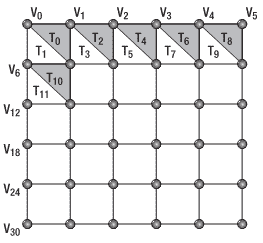
图10-4. 创建三角形的顶点索引
地形上的每个四边形有两个三角型:一个灰色一个白色。灰色三角形的顶点索引是0、1和7,而白色三角形是0、7和6。注意三角形索引的顺序是重要的:必须是顺时针,因为XNA素材管道默认会剔除逆时针方向的三角形。每个正方形中的第一个和第二个三角形的顶点顺序由下列方程决定:
Ttop=V[index],V[index+1],V[index+VertexCountX+1]
Tbottom=V[index],V[index+VertexCountX+1],V[index+VertexCountX]
译者注:原文是Tbottom=V[index],V[index+1],V[index+VertexCountX+1],Ttop=V[index],V[index+VertexCountX+1],V[index+VertexCountX],怀疑是笔误。
在前面的方程中,VertexCountX等于顶点网格的行数,使用这个方程你可以遍历所有正方形生成对应三角形的索引。将顶点索引存储在一个整数数组中。以下是GenerateTerrainIndices方法的代码:
private int[] GenerateTerrainIndices()
{
    int numIndices = numTriangles * 3;
    int[] indices = new int[numIndices];
    int indicesCount = 0;
    for (int i= 0; i<(vertexCountZ - 1); i++)
    {
        for (int j= 0; j<(vertexCountX - 1); j++)
        {
            int index = j+ i* vertexCountZ;

            // First triangle
            indices[indicesCount++] = index;
            indices[indicesCount++] = index + 1;
            indices[indicesCount++] = index + vertexCountX + 1;

            // Second triangle
            indices[indicesCount++] = index + vertexCountX + 1;
            indices[indicesCount++] = index + vertexCountX;
            indices[indicesCount++] = index;
        }
    }
    return indices;
}
生成顶点位置和纹理坐标
本节你将创建GenerateTerrainVertices方法生成顶点。你将地形放置在XZ平面,将地形中心点放置在(0,0)上。要做到这点,你必须首先计算地形在X和Z轴方向的一半大小,并将地形的开始位置在X和Z方向上减去(-halfTerrainWidth,-halfTerrainDepth)一半大小。你可以通过vertexCountX、vertexCountZ和blockScale计算地形大小,计算出大小,将它除以2,如下所示:
float terrainWidth = (vertexCountX - 1) * blockScale;
float terrainDepth = (vertexCountZ - 1) * blockScale;
float halfTerrainWidth = terrainWidth * 0.5f;
float halfTerrainDepth = terrainDepth * 0.5f;
你可以从地形开始点生成顶点网格并遍历每行每列放置顶点(从-X到+X,从-Z到+Z)。通过这种方式,顶点网格根据你定义的blockScale沿X和Z轴依次放置,如图10-2所示。当放置顶点时,你还要使用存储在高度图中的数据设置沿Y轴方向的顶点高度。你也可以乘以一个缩放因子heightScale改变顶点的高度,以下是代码:
for (float i=-halfTerrainDepth; i<= halfTerrainDepth; i+= blockScale)
    for (float 	j=-halfTerrainWidth; j<= halfTerrainWidth; j+= blockScale)
        Position = (j, heightmap[vertexCount] * heightScale, i)
每个顶点还有一个范围在(0, 0) 和 (1, 1) 之间的UV纹理坐标,(0, 0)代表纹理初位置,(1, 1)代码末位置,图10-5展示了纹理坐标:
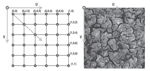
图10-5:左图是顶点网格的纹理坐标,右图是纹理贴图上的UV轴
要计算正确的纹理坐标,首先应计算UV轴上的纹理坐标增量,你可以在每根轴上将最大纹理坐标值(1. 0)除以顶点数减1:
	float tu = 0;
float tv = 0;
float tuDerivative = 1.0f / (vertexCountX - 1);
float tvDerivative = 1.0f / (vertexCountZ - 1);
然后遍历每个顶点,设置纹理坐标并增加相应数量。除了位置和纹理坐标,你还要计算法线、切线和副法线,因此还有创建GenerateTerrainNormals和GenerateTerrainTangentBinormal方法,这两个方法在GenerateTerrainVertices方法最后被调用,下面是GenerateTerrainVertices的完整代码:
private VertexPositionNormalTangentBinormal[] GenerateTerrainVertices( int[] terrainIndices)
{
     float halfTerrainWidth =(vertexCountX - 1) * blockScale * 0.5f;
     float halfTerrainDepth =(vertexCountZ - 1) * blockScale * 0.5f;

     // Texture coordinates
     float tu = 0;
     float tv = 0;
     float tuDerivative = 1.0f / (vertexCountX - 1);
     float tvDerivative = 1.0f / (vertexCountZ - 1);
     int vertexCount = 0;

     // Create the vertex array
     VertexPositionNormalTangentBinormal[] vertices = new VertexPositionNormalTangentBinormal[vertexCountX * vertexCountZ];
     // Set position and texture coordinate of each vertex
     for (float i=-halfTerrainDepth; i<= halfTerrainDepth; i+= blockScale)
     {
         tu = 0.0f;
         for (float j=-halfTerrainWidth; j<= halfTerrainWidth; j+= blockScale)
         {
             // Set vertex position and UV
             vertices[vertexCount].Position =new Vector3(j, heightmap[vertexCount] * heightScale, i);
             vertices[vertexCount].TextureCoordinate = new Vector2(tu, tv);
             tu += tuDerivative; vertexCount++;
         }
         tv += tvDerivative;
     }
     // Generate vertices' normal, tangent, and binormal
     GenerateTerrainNormals(vertices, terrainIndices);
     GenerateTerrainTangentBinormal(vertices, terrainIndices);
     return vertices;
}
生成顶点法线
三角形中的每个顶点的法线等于三角形的法线。所以要计算顶点的法线,你需要计算三角形的法线。因为叉乘可以获得垂直于两相交向量的向量,所以你可以通过叉乘由顶点构成的两个向量计算出法线,比如(v1 – v0) 和 (v2 – v0)。因为Because one to six different triangles不同的三角形共享每个顶点,每个顶点的法线是共享这个顶点的三角形的法线之和,所以你需要计算每个三角形的法线并把它们求和。最后你还应归一化每个法线。法线向量用于光照计算,你必须做归一化处理才能产生正确的光照效果。下列在GenerateTerrainNormals方法中的代码用于生成顶点法线:
private void GenerateTerrainNormals(VertexPositionNormalTangentBinormal[] vertices,int[] indices)
{
    for (int i= 0; i< indices.Length; i+= 3)
    {
        // Get the vertex position (v1, v2, and v3)
        Vector3 v1 = vertices[indices[i]].Position;
        Vector3 v2 = vertices[indices[i + 1]].Position;
        Vector3 v3 = vertices[indices[i + 2]].Position;

        // Calculate vectors v1->v3 and v1->v2 and the normal as a cross product
        Vector3 vu = v3 - v1;
        Vector3 vt = v2 - v1;
        Vector3 normal = Vector3.Cross(vu, vt);
        normal.Normalize();

        // Sum this normal with the current vertex normal of the tree vertices
        vertices[indices[i]].Normal += normal;
        vertices[indices[i + 1]].Normal += normal;
        vertices[indices[i + 2]].Normal += 	normal;
   }
   // After calculating all the normals, normalize them
   for (int i= 0; i< vertices.Length; i++)
   vertices[i].Normal.Normalize();
}
生成顶点切线和副法线
自定义effect使用法线映射,这种方法可以在不增加网格复杂度的前提下添加地形的细节。要使用法线映射,所有顶点必须包含切线、副法线和法线向量,这三个向量是正交的,它们构成了基本三角形。图10-6展示了两个不同表面的不同点上的这三个向量。
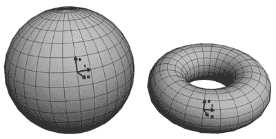
图10-6 切线、副法线和法线向量
因为切线向量是从该顶点出发终止于网格上的相邻顶点,所以你可以计算每个顶点的切线向量,切线向量是指向X轴方向的。注意最后一个顶点的切线向量的起始点是倒数第二个顶点,终止于最后一个顶点。 计算完切线向量后,你可以通过叉乘切线和法线向量获得副法线向量。图10-7显示了在一个平面顶点网格上的切线、副法线和法线向量。
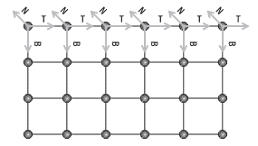
图10-7 一个平面顶点网格上的切线、副法线和法线向量
在GenerateTerrainTangentBinormal方法中使用以下代码计算切线和副法线:
public void GenerateTerrainTangentBinormal( VertexPositionNormalTangentBinormal[] vertices, int[] indices)
{
    for (int i= 0; i< vertexCountZ; i++)
    {
         for (int j= 0; j< vertexCountX; j++)
         {
             int vertexIndex = j+ i* vertexCountX;
             Vector3 v1 = vertices[vertexIndex].Position;

             // Calculate the tangent vector
             if (j < vertexCountX - 1)
             {
                 Vector3 v2 = vertices[vertexIndex + 1].Position;
                 vertices[vertexIndex].Tanget = (v2 - v1);
             }

             // Special case: Last vertex of the plane in the X axis
             else
             {
                 Vector3 v2 = vertices[vertexIndex - 1].Position;
                 vertices[vertexIndex].Tanget = (v1 - v2);
              }

              // Calculate binormal as a cross product (Tangent x Normal)
              vertices[vertexIndex].Tanget.Normalize();
              vertices[vertexIndex].Binormal = Vector3.Cross( vertices[vertexIndex].Tanget,vertices[vertexIndex].Normal);
        }
    }
}
发布时间:2009/4/21 15:33:38 阅读次数:9978